
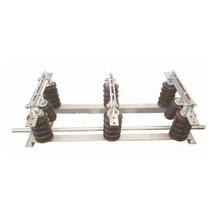
Home / Products / Indoor High-Voltage / High Voltage Disconnect Switch / FKN12A-12/FKRN12A-12 compressed air load switch
High Voltage Disconnect Switch
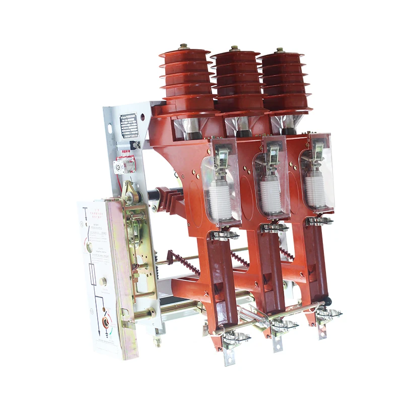
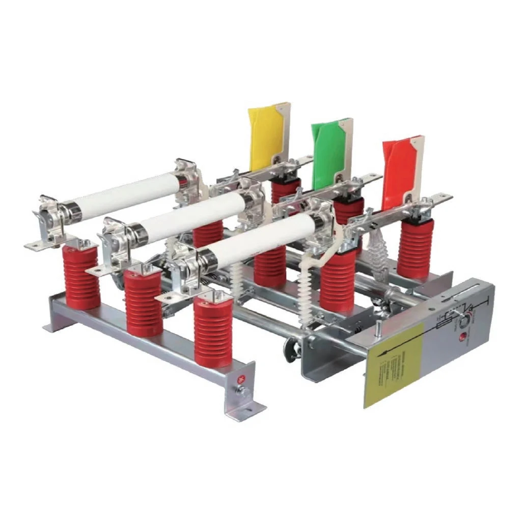
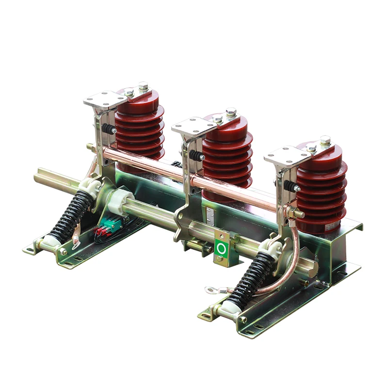
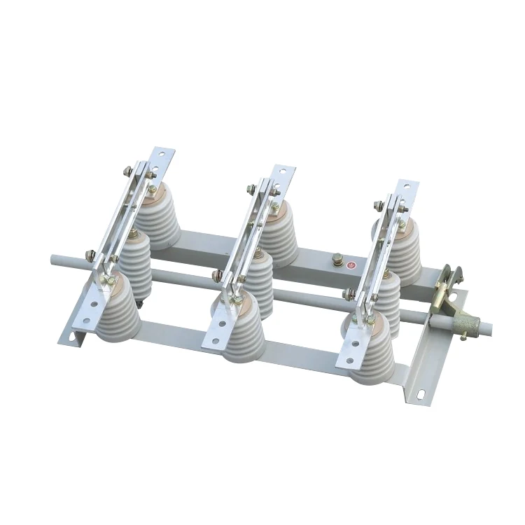
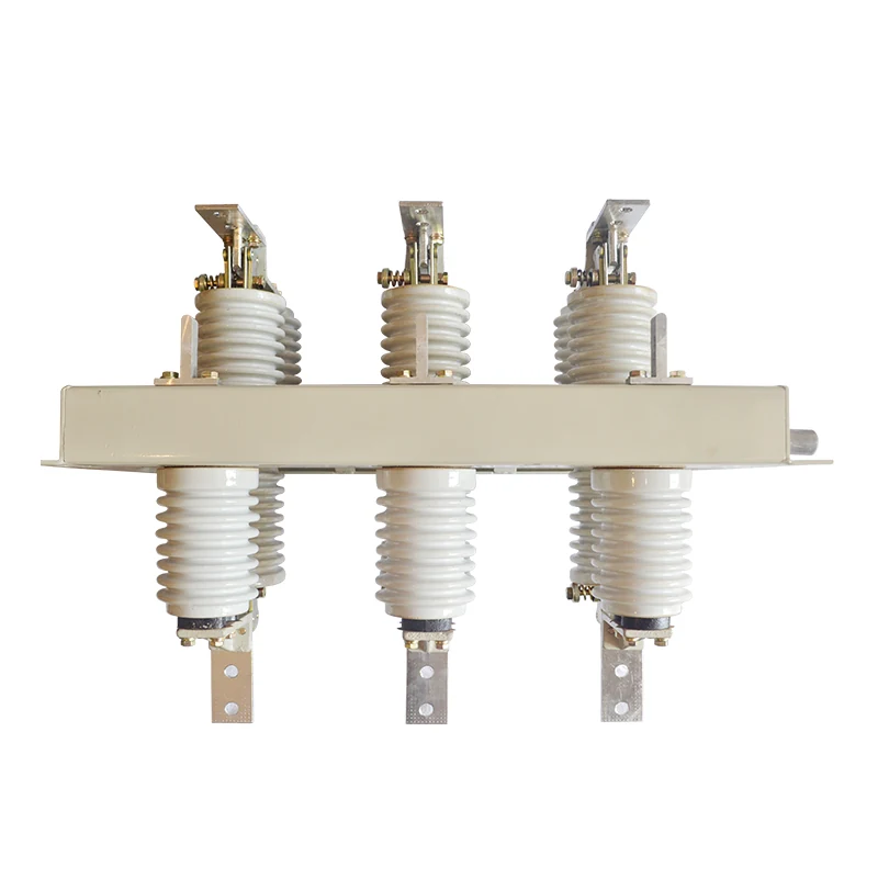
FKN12A-12/FKRN12A-12 compressed air load switch
FKN12A-12/FKRN12A-12 compressed air load switch
Project-focused selection
Support matched to operating conditions and project requirements.
Quality-controlled supply
Clear communication from confirmation through delivery.
Export service
Documentation and shipping support for overseas buyers.
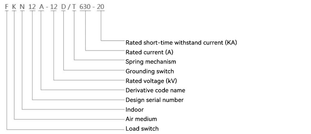
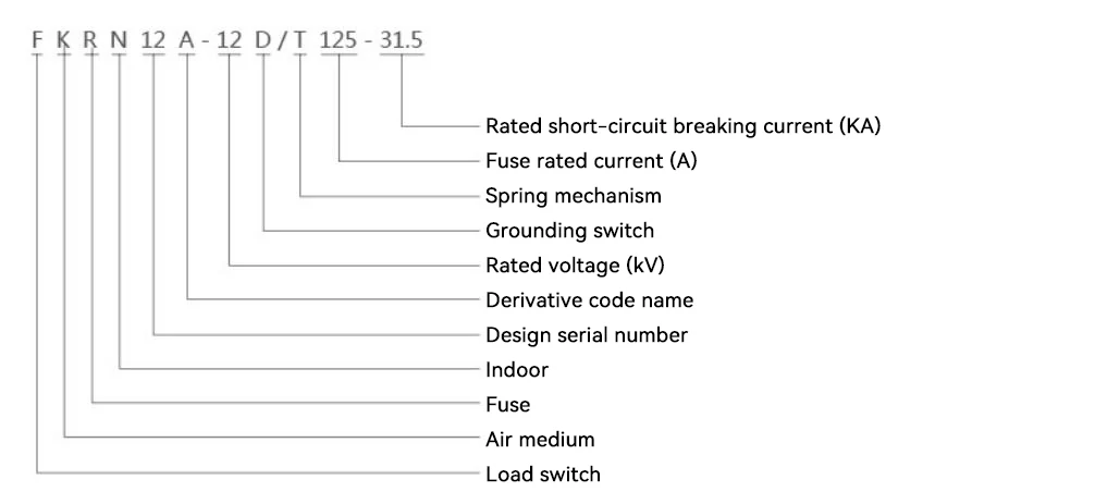
Model and Meaning
Main uses
The FKN12A-12D pneumatic load switch, part of the FKRN12A-12D series, is a pneumatic load switch-fuse combination appliance suitable for use in 12kV and below three-phase power distribution systems for the control and protection of power equipment such as transformers, cables, and overhead lines. It is particularly suitable for terminal substations and prefabricated substations in urban and rural power grids. It is also suitable for the control and protection of ring networks and dual-radial power supply units.
The FKN12A-12D series pneumatic load switches can switch on and off load currents and overload currents.
The FKRN12A-12D series pneumatic load switch-fuse combination appliance can switch on and off load current, overload current, and interrupt short-circuit current.
Environmental conditions for use
◆Air temperature: -25℃~+40℃;
◆Altitude: Not exceeding 1000m;
◆Relative humidity: Daily average not exceeding 95%, monthly average not exceeding 90%;
◆Earthquake intensity: Not exceeding magnitude 8;
◆Installation Location: Locations free from fire, explosion hazards, chemical corrosion, and severe vibration;
◆Dirty level: Ⅱ.
Structural features
◆ The load switch, grounding switch, fuse, and mechanism are integrated into a single frame, allowing for flexible combination, a compact structure, small size, and easy installation;
◆The break point is a direct-acting type, with high dynamic and thermal stability current parameters, completing the operation in one step:
◆Featuring a static contact insulation cover, the ring main unit achieves structural isolation, eliminating the need for phase-to-phase insulation partitions and break-point insulation inserts, thus preventing arcing short-circuit accidents within the unit;
◆Features a unique valve structure; after the load switch is tripped, the valve automatically isolates the break, providing excellent protection.
◆The load switch, grounding switch, and fuse have reliable mechanical interlocking devices to meet the "five protections" requirements;
◆ It has two modes of operation: manual operation and electric operation with AC/DC dual-power supply, which facilitates the realization of the "three remote" requirements of the power system.
Main technical parameters
| Project | Unit | FKN12A-12D | FKRN12A-12D | ||
| Rated voltage | kV | 12 | 12 | ||
| Rated frequency | Hz | 50 | 50 | ||
| Rated current | A | 630 | 150 | ||
| Rated insulation level | 1 min power frequency withstand voltage | Ground-to-ground, inter-regional | kV | 42 | 42 |
| Rated insulation level | 1 min power frequency withstand voltage | Isolation break | kV | 48 | 48 |
| Rated insulation level | Lightning impulse withstand voltage (peak value) | Ground-to-ground, inter-regional | kV | 75 | 75 |
| Rated insulation level | Lightning impulse withstand voltage (peak value) | Isolation break | kV | 85 | 85 |
| Load switch | KA | 20 | – | ||
| Grounding switch | KA | 20 | 20 | ||
| Load switch | S | 4 | – | ||
| Grounding switch | S | 2 | 2 | ||
| Rated short-circuit making current (peak value) | KA | 50 | – | ||
| Rated breaking current | Active load breaking current | A | 630 | – | |
| Rated breaking current | Closed-loop interrupting current | A | 630 | – | |
| Rated breaking current | 5% active load breaking current | A | 31.5 | – | |
| Rated breaking current | Cable charging current | A | 10 | – | |
| Rated breaking current | Breaking off no-load transformer capacity | kVA | 1250 | 1250 | |
| Rated short-circuit breaking current (current-limiting fuse) | KA | – | 31.5 | ||
| Rated transfer current | A | – | 1200 | ||
| Mechanical life | 次 | 2000 | 2000 | ||
| Impactor output energy | J | – | 1+0.5 | ||
| Project | Unit | Parameter |
| Fracture opening distance | mm | ≥ 175 |
| Interphase center distance | mm | 210±2 |
| Interphase air gap | mm | ≥ 125 |
| Journey | mm | 210±4 |
| Over-trip | mm | ≥ 40 |
| Three-phase closing not synchronized | ms | ≥10 |
| Three-phase tripping not synchronized | ms | ≤ 5 |
| The shunt trip unit's inherent tripping time | ms | 40~65 |
| Main circuit resistance | μΩ | ≤ 130 |
Related Products
Explore more products from the same category.
Project inquiry
Tell Us What Your Project Needs
Include the voltage level, quantity, application and destination market for a faster response.